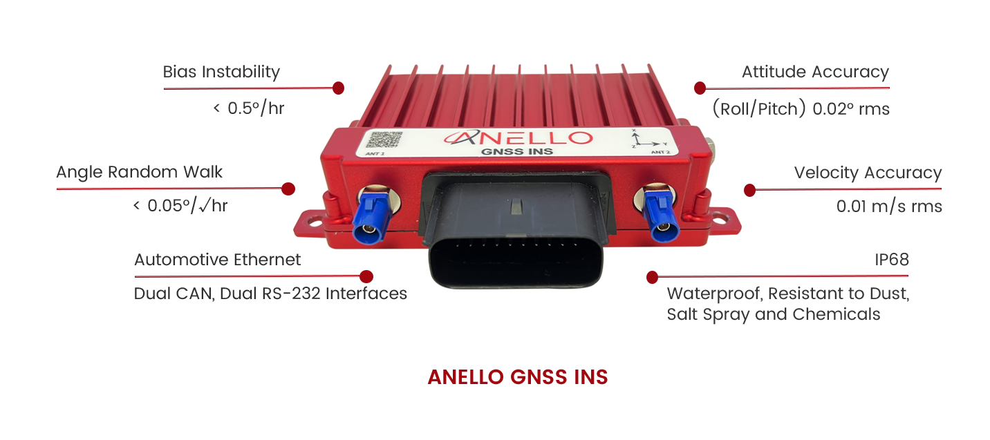
ANELLO GNSS INS

OPTICAL GYRO TECHNOLOGY FOR GNSS-DENIED INERTIAL NAVIGATION AND LOCALIZATION

INTRODUCTION

The ANELLO GNSS INS was built for Long-Term GNSS-Denied Navigation and Localization. The ANELLO GNSS INS delivers robust high-accuracy positioning and orientation for applications in the Agriculture, Construction, Trucking and Autonomous Vehicle space.

UNLOCK PRECISION WITH THE ANELLO GNSS INS

Learn The Benefits of The ANELLO GNSS INS

Experience The ANELLO GNSS INS Test Drive Without GPS

The ANELLO GNSS INS benefits several industries, particularly those requiring reliable navigation in GPS-denied environments. Key industries include:

  • Agriculture : Provides high-precision navigation for autonomous tractors and vehicles in areas with unreliable GPS, such as orchards.
  • Construction : Ensures accurate positioning for machinery in challenging environments.
  • Trucking : Supports navigation for long-haul vehicles where GPS signals may be obstructed.
  • Autonomous Vehicles : Offers critical navigation solutions for vehicles operating in urban or remote areas.
  • Defense : Used in unmanned aerial and land vehicles where GPS signals may be compromised.
ANELLO GNSS INS

KEY FEATURES

  • Reference-grade 100 Hz Position, Velocity and Attitude
  • < 0.5º/hr Unaided Heading Drift
  • Accurate in severe multipath and GNSS-denied
  • Dual 184-channel five constellation dual-band GNSS Receivers
  • GPS, Glonass, Galileo, Beidou (Compass), QZSS
  • Reliable Autonomous Land Vehicles, Advanced ADAS Systems
  • Automotive, Precise Heavy Equipment and Machine Control
  • Hardware PTP Time Sync, ASIL-D CPU and OS
  • Modular Dual-Band RTK-capable Multi-Band GNSS Engines
  • On-Board GNSS/INS Sensor Fusion
  • IP68 - Waterproof, Resistant to Dust, Salt Spray and Chemicals
  • Automotive Ethernet, Dual RS-232 Interfaces

SPECIFICATIONS

Horizontal Position Accuracy1
SPS………………………………………………………………1.2 m cep
RTK2……………………………………………………………0.02 m cep
60s GNSS Outage3…………………………< 1.0 m rms
Velocity Accuracy…………………………………………0.01 m/s rms
Heading Accuracy4………………………………………0.2° rms
Attitude Accuracy (Roll/Pitch)………………0.02° rms


Notes:
1. After Initialization
2. < 20km Baseline from Base
3. Additional Drift Post GNSS Loss, with Wheel Speed Aiding
4. Properly Installed Antennae
IMU Performance
Optical Gyroscope (Heading/Z-Axis)
Range………………………………………………………… 200°/s
Bias Instability……………………………………….< 0.5°/hr
Angle Random Walk……………………… < 0.05°/√hr
MEMS IMU (6-Axis)…………………………… Accelerometer
Range………………………………………………………… 8g
Bias Instability……………………………………… 20ug
Random Walk……………………………………… 0.03m/s/√hr
Gyroscope
up to 400°/s
1.5°/hr
0.3°/√hr
Optical Gyroscope (Heading/Z-Axis)
Range………………………………………………………… 200°/s
Bias Instability……………………………………….< 0.5°/hr
Angle Random Walk……………………… < 0.05°/√hr
MEMS IMU (6-Axis)……………………………………………Accelerometer Gyroscope
Range………………………………………………………………………….8g, up to 400°/s
Bias Instability…………………………………………………… 20ug, 1.5°/hr
Random Walk…………………………………………………………0.03m/s/√hr, 0.3°/√hr
GNSS & Timing
Signal Bands……………………… L1 C/A, L2C, L1OF, L2OF, B1I, B2I, E1, E5b and SBAS
RTK Initialization Time…. <1 min, using RTCM3 corrections
Output Data Rate…………………… GPS: 4 Hz, IMU: 200 Hz, INS: 100 Hz
Synchronization…………………………PPS Out, PPS Sync In, PTP
Environment
Operating Temperature ………………….-40 to +70°C
Vibration ………………………………………………………… 5g rms
Shock Survival ………………………… 40g
Electrical
Input Voltage …………………………………… 8 to 30 VDC
Power Consumption …………………… 4 W typical
Digital Interface ………………. Ethernet, RS-232 (2 Ports)
Physical
Size……………………………………. 5.8” x 4.3” x 1.3”
Weight……………………………. 1 lbs.